Method
More details about the compositional deadlock detection and verification method implemented in the D-Finder tool can be found here.
How To Install and Run D-Finder
Requirements:
- Linux or Mac OS X.
- Java 1.6.
The installation of D-Finder requires the following steps:
- First dowload the D-Finder tool-set
- Extract the package.
- Follow the instructions in the INSTALL file to install and configure the third party tools Yices, Omega, and JavaBDD
- Build your BIP model (here is an example of Dining Philosopher in BIP). More information about BIP modeling framework can be found here.
- Go to the DFinder directory and run the D-Finder tool to verify your model by the following command:
- For global methods:
./dfinder -c dfinder.config -f [path-to-model.bip] --method=[pm/linear] - For incremental methods:
./dfinder -c dfinder.config -f [path-to-model.bip] --incr_file [incr-file] --method=[pm]
where: -
pm: symbolic method based on positive mapping -
linear: computes linear invariants that might be stronger but is not efficient for large-scale/complex systems. -
[incr-file]: file that defines set of increments
- For global methods:
News: a GUI for D-Finder has been available (for both Linux and Mac OS X). In DFinder directory, run the following script:
./dfinder-gui
Running Examples
Dining Philosopher
in Terminal, go to D-Finder folder run the global methods by the following command:
./dfinder -c dfinder.config -f examples/philo20.bip --method=pm/fp/linearor run the incremental methods by the following command:
./dfinder -c dfinder.config -f examples/philo20.bip -incr_file examples/philo20.incr --method=pm/fpTemperature Control
in Terminal, go to D-Finder folder run the following command:
./dfinder -c dfinder.config -f examples/tempcontrol.bip --method=pm --analysis dlCase Studies
Dining Philosophers
The Dining Philosophers problem, illustrated in Fig. 1 (a), can be shortly presented as a number of philosophers sitting at a table doing one of two things: eating or thinking. While they are thinking, they are not eating and while they are eating, they are not thinking. They sit at a round table and each philosopher has a spaghetti disk in front of him. Between two any next philosophers, there is a fork. A philosopher can eat if he has both forks from the left and from the right. And a philosopher can put two forks back to the table only if he has finished eating. Here there is a deadlock situation if they all have the same order of taking forks and every philosopher has taken one fork, so everyone can not eat because each has only one fork.
Fig. 1: (a) Dining Philosophers - (b) Philosopher Component - (c) Fork Component
However, if a Philosophers changes the order of taking forks, for example, he takes the right one before the left one while the others take the left one before the right one, then there is no deadlock. We have considered both cases in the experimentation.
We have modeled the philosopher and the fork in BIP. Fig. 1 (b) represents the behavior of a philosopher: initially in state lth, he can think by think transition or prepare for eating by first taking the left fork (take_l transition) and moves to l1f location where he has one fork on the left hand, then taking the right fork (take_r transition) and moves to l2f location where he has two forks on both hands. At l2f he can eat by taking eat transition and moves to lfi location where he has finished eating, hence he can put two forks by put transition and returns to lt location. The think and the eat transitions are internal, they can be executed without synchronizing with other components and hence their ports are complete, represented by triangles in the figure. The other ports (take_l, take_r, put) are incomplete (represented by circles) and their transitions need to synchronize with other components to be executed.
The model of a fork is quite simple (Fig. 1 (c)): it has two locations lf and lu. Initially in the location lf , a fork can be taken by use transition and goes to lu location. From lu, a fork is released if the free transition is executed and the fork returns to lf location. Both ports use and free are incomplete.
Incremental Verification
Fig. 2 shows the model for Dinning Philosophers with 4 Philosophers and 4 forks. In general case, given n philosophers and n forks, the interactions are:
where th_i, t_li, t_ri, e_i, p_i respectively represent the ports think, take_l, take_r, eat, put of Philosopher philo_i, and u_i, fr_i respectively represent the ports use, free of Fork fork_i. In the incremental construction, these interactions can be obtained from the superposition of a set of increments, each increment adds interactions for philosophers from n_1 to n_2 with 1 <= n_1,n_2 <= n as follows:
For example, the set of interactions for a system of 4 Philosophers is the superposition of the two following increments:
Experimental Results
The table below provides an overview of the experimental results obtained for the Dining Philosophers. For the columns: scale is the number Philosophers, comps is the number of BIP components, locs is the total number of control locations, intrs is the total number of interactions, Enum is the verification time by the enumerative method implemented in D-Finder 1, PM, FP, IPM, IFP are respectively times consumed by Positive Mapping, Fixpoint, Incremental Positive Mapping, Incremental Fixpoint methods implemented in D-Finder 2. NuSmv and Spin are respectively the verification time by NuSmv and Spin tools. Verification times are given in minutes. Timeout, i.e., "-" is one hour.
| scale | comps | locs | intrs | Enum | PM | FP | IPM | IFP | NuSmv | Spin |
|---|---|---|---|---|---|---|---|---|---|---|
| 100 philos | 200 | 600 | 500 | 0:06 | 0:09 | - | 0:03 | 0:21 | 0:50 | - |
| 500 philos | 1000 | 3000 | 2500 | 1:51 | 3:32 | - | 0:22 | 3:09 | - | - |
| 1000 philos | 2000 | 6000 | 5000 | 7:08 | 14:57 | - | 0:50 | 19:05 | - | - |
| 1500 philos | 3000 | 9000 | 7500 | 19:30 | 34:23 | - | 1:34 | - | - | - |
| 3000 philos | 6000 | 18000 | 15000 | - | - | - | 4:57 | - | - | - |
Gas Station
Gas Station consists of an Operator with a computer, a set of pumps, and a set of customers. Each pump can be used by a fixed number of customers.
Before using a pump, each customer has to prepay for the transaction. Then the customer uses the pump, collects his change and goes to a state from which he may start a new transaction.
Before being used by a customer, the pumps have to be activated by the Operator. When a pump is shut off, it can be re-activated for the next operation.
Figure 6.7 gives the model for Gas Station system for one pump and two customers. The Operator has two control locations and three ports.The transition labeled with prepay accepts a customer’s prepay and activates the pump for the customer. When a customer is served, the transition labeled with finish will synchronize the pump and the customer. A pump has three control locations and three ports. Besides the synchronization between the Operator and customer through activate and finish ports, a pump and a customer are synchronized through start ports.
Incremental Verification
We abbreviate port names by using only their first three letters. The ports of Operator are respectively $pre$, $fin$, $cha$; the ports of $pump_i$ are respectively $act_i$, $sta_i$, $fin_i$ and the ports of customer_j of pump_i are pre_ij, sta_ij, fin_ij, cha_ij. The interactions for a system of $n$ pumps, each one used by $m$ customers, are
The system consisting of $n$ pumps and $m$ customers can be incrementally built by the superposition of a set of increments, each increment adds interactions for a set of pumps, a set of customers and Operator. If each pump connects to $m$ customers, the increment that adds interactions for the pumps from $n_1$ to $n_2$ is:
For example, the system of two pumps and two customers can be built from two increments, each increment contains interactions over a pump, a customer and Operator as follows:
Experimental Results
The table below provides an overview of the experimental results obtained for Gas Station. For the columns: scale is the number pumps (every pum has 10 custumers), comps is the number of BIP components, locs is the total number of control locations, intrs is the total number of interactions, Enum is the verification time by the enumerative method implemented in D-Finder 1, PM, FP, IPM, IFP are respectively times consumed by Positive Mapping, Fixpoint, Incremental Positive Mapping, Incremental Fixpoint methods implemented in D-Finder 2. NuSmv is the verification time by NuSmv tool. Verification times are given in minutes. Timeout, i.e., "-" is one hour.
| scale | comps | locs | intrs | Enum | PM | FP | IPM | IFP | NuSmv |
|---|---|---|---|---|---|---|---|---|---|
| 3 pumps - 100 custumers | 104 | 414 | 400 | 0:10 | 0:08 | 0:08 | 0:09 | 0:07 | 0:10 |
| 3 pumps - 150 custumers | 154 | 614 | 600 | 0:27 | 0:20 | 0:15 | 0:16 | 0:10 | 0:47 |
| 3 pumps - 200 custumers | 254 | 814 | 800 | 0:32 | 0:28 | 0:20 | 0:20 | 0:15 | - |
| 300 pumps - 3000 custumers | 3301 | 12902 | 12000 | 33:02 | 36:01 | 11:32 | 2:03 | 4:18 | - |
| 400 pumps - 4000 customers | 4401 | 17202 | 16000 | - | - | 21:40 | 3:41 | 10:30 | - |
| 500 pumps - 5000 customers | 5501 | 21502 | 20000 | - | - | - | 5:48 | 20:05 | - |
ATM
Automatic Teller Machine (ATM) is a computerized telecommunication device that provides services to access to financial transactions in a public space without the need for a cashier, human clerk or bank teller. The structural model of the ATM system is presented in Figure 1. The system is composed of the following components: User, ATM (modeling a cash dispenser) and Bank (modeling some aspects of bank operation). User and Bank interact only with ATM, but not with each other.
Figure 2 presents the modeling of ATM in BIP: Initially at location l0, user can insert the card by insert transition and enter the confidential code (enter transition). Then there are two cases: if the code is invalid, user gets back the card by eject transition and returns to the initial state l0; otherwise, user continues by entering the amount of cash he/she wants to withdraw. If the amount is not accepted, the transaction is canceled (cancel transition); else there are two cases: transition fails (fail transition) or is ready (success transition) for user to withdraw the money. Finally user gets back their card. Initially at location l0, ATM is waiting for user to insert the card (insert transition) and then to enter the confidential code (enter transition). The time-out for entering the code is 5 time units then it validates the entered code. If it receives non-authorized for the code by non_authorized transition, invalid transition takes place and then it ejects the card. If it receives authorized signal by authorized transition, the transition validated takes place and it moves to a location where user can enter the amount of cash. The timeout for entering the amount is 6 time units. If the user cancels the transaction or the amount is not allowed, it returns to l6 to eject the card; else it accepts the amount and starts the transaction. If the transaction is forbidden (veto transition), it will announce to user by fail transition; else it will wait for user to withdraw the cash (withdraw transaction) and eject the card to finish the transaction. For Bank, there are two components: BankValidation component checks the validity of PIN code and BankTransaction component checks whether the transaction is forbidden (veto) or allowed (fiat). The use of these parallel components allows supporting multi Users and multi ATMs.
Experimental Results
The table below provides an overview of the experimental results obtained for ATM. For the columns: scale is the number atm machines, comps is the number of BIP components, locs is the total number of control locations, intrs is the total number of interactions, Enum is the verification time by the enumerative method implemented in D-Finder 1, PM, FP, IPM, IFP are respectively times consumed by Positive Mapping, Fixpoint, Incremental Positive Mapping, Incremental Fixpoint methods implemented in D-Finder 2. Verification times are given in minutes. Timeout, i.e., "-" is one hour.
| scale | comps | locs | intrs | Enum | PM | FP | IPM | IFP |
|---|---|---|---|---|---|---|---|---|
| 2 atms | 6 | 48 | 38 | 0:59 | 0:05 | 0:02 | 0:02 | 0:02 |
| 20 atms | 42 | 444 | 362 | - | 1:12 | 1:00 | 0:43 | 1:13 |
| 50 atms | 102 | 1104 | 902 | - | 7:14 | 8:00 | 1:57 | 11:22 |
| 100 atms | 202 | 2204 | 1802 | - | - | - | 4:60 | - |
| 200 atms | 402 | 4404 | 3602 | - | - | - | 17:07 | - |
Dala Robot
Robot Dala, an iRobot ATRV, has been developed at LAAS laboratory. It is composed of three layers (Figure 6.13):
- Functional layer includes all the basic built-in robot actions and perception capacities (image processing, motion control, etc.)
- Decisional layer produces the task plan and supervises its execution.
- Control layer is an interface between the decisional and functional layers that controls the execution of services in the functional layer according to some safety constraints.
We have used BIP to model the execution control layer and functional layer of the robot Dala. The functional layer consists of a set of modules. A module has a set of services, a set of execution tasks and a set of posters where the produced data is stored. A service has a controller and an activity. An execution task is composed of a timer, a scheduler and an activity. We proposed the following grammar which allows building the functional level starting from basic components:
| Functional level | ::= | (Module)+ | |
| Module | ::= | (Service)+.(Execution task)+.(Poster)+ | |
| Service | ::= | (Service controller).(Activity) | |
| Execution task | ::= | (Timer).(Scheduler activity) |
where + (plus) means the presence of one or more subcomponent and . (dot) means the composition of different components.
NDD Module
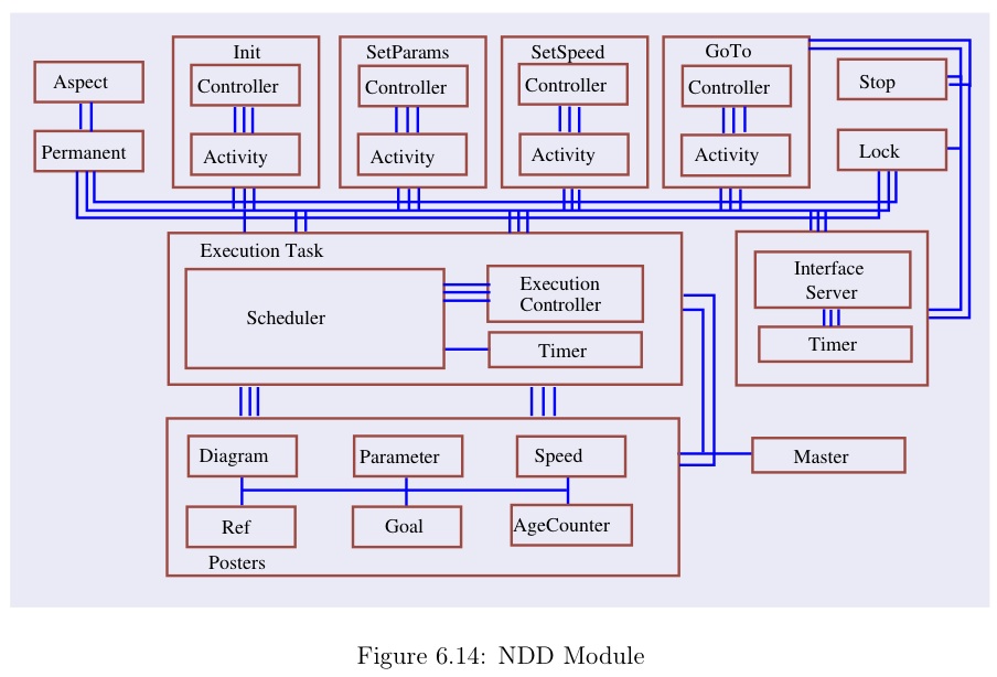
We have used BIP to model eight modules in the functional level of Dala Robot and D-Finder to check deadlock-freedom of these module. One of the most complex module is NDD, which is responsible for the navigation of the robot, that is to reach a goal while avoiding obstacles. It has totally 27 components, 144 control locations, 117 connectors between components, 16 boolean variables and 11 integer variables. It consists of the following control elements:
- InterfaceServer is the interface of the module with the decisional layer. It checks the mailbox which is a shared memory and if there is any message, it will read the content and then sends requests to the corresponding service.
- ExecutionControl keeps information about the number of services running in the module. If a service is triggered, it increases the number by 1, if a service finishes, it decreases the number by 1.
- ExecutionTask runs periodically to synchronize the executions of different services, that is different services can be executed within a period but a service can not be executed more than one time within a period.
and the following services:
- PermanentTask computes the speed of the robot and it is executed periodically during the execution of the robot.
- Init service initializes the module.
- SetParams service sets the necessary parameters of the module.
- SetSpeed service sets the moving speed of the robot which is computed by PermanentTask.
- GoTo service allows the robot moving to a given destination.
- Stop service allows stopping the robot at any time.
NDD also has a set of components called Poster (SpeedPoster, ParamPoster, DiagramPoster, AspectPoster, RefPoster, GoalPoster, AgePoster, MasterPoster) where data produced by the services of the module is stored and exchanged between different services of NDD or with services of other modules.
A Basic Service of Dala
A service basically has two components (Figure 6.15): a Controller and an Activity. The Controller receives requests (trigger transition), checks parameters and execution conditions (control transition) and if everything is fine, the Controller will trigger the Activity (start transition) to perform the request. The Controller can cancel the request if there is an error (error transition) or conflict (abort transition). The Controller updates the status of the Activity by finish, inter and fail transitions. And finally, it sends a report (send_final_report transition) to the ExecutionControl component.
The Activity is triggered by the Controller (start transition) and then it executes its functions to perform the requested task (exec, internal_exec transitions). The execution may finish normally (finish transition), may fail (fail transition) or may be interrupted (inter transition). In any case, the Activity informs the result to the Controller.
Verification Results
There are eight modules described with the BIP language that are running in DALA. Their functions are (1) collecting data from the laser sensors (SICK), (2) generating an obstacle map (Aspect), (3) navigating using the near diagram approach (NDD), (4) managing the low level robot wheel controller (RFLEX), (5) emulating the communication with an orbiter (Antenna), (6) providing power and energy for the robot (Battery), (7) heating the robot in a low temperature environment (Heating) and (8) controlling the movement of two cameras (Platine). All together the embedded code of DALA contains more than 500 000 lines of C code. The topology of the modules and the description of the behaviors of the components are complex. This is beyond the scope of tools such as NuSMV or SPIN. We first checked deadlock properties of individual modules. Both global and FP fails to check for deadlock-freedom. However, by using Incr, we can always generate the invariants and check the deadlock-freedom of all the modules. Table below shows the time consumption in computing invariants for deadlock-freedom checking of seven modules by the incremental method; it also gives the number of states per module. In these modules we have successively detected (and corrected) two deadlocks within Antenna and NDD, respectively.
The table below provides an overview of the experimental results obtained for the modules of Dala robot. For the columns: Module is the name of module, comps is the number of BIP components, locs is the total number of control locations, intrs is the total number of interactions, b is the number of boolean variables, int is the number of integer variables. The method used to verify these modules is Incremental Positive Mapping (IPM). Verification times are given in minutes. Timeout, i.e., "-" is one hour.
| Module | comp | inters | locs | b | int | dls | time (m:s) |
|---|---|---|---|---|---|---|---|
| RFLEX | 56 | 227 | 308 | 30 | 16 | 0 | 3:07 |
| NDD | 27 | 117 | 152 | 16 | 10 | 0 | 1:15 |
| Sick | 43 | 202 | 213 | 18 | 10 | 0 | 1:04 |
| Aspect | 29 | 117 | 160 | 16 | 11 | 0 | 0:21 |
| Antenna | 30 | 138 | 176 | 21 | 11 | 0 | 4:43 |
| Combined | 198 | 724 | 926 | 101 | 70 | 0 | 5:05 |
Aside from the deadlock-freedom requirement, some modules also have safety property requirements such as causality (a service can be triggered only after a certain service has been running successfully, i.e., only if the variable corresponding to this service is set to true). In checking the causality requirement between different services, we need to compute invariants according to different causality requirement. Inspired from the invariant preservation properties, we removed some tight synchronizations between some components that would not synchronize directly with the components involved in the property and obtained a module with looser synchronized interactions. As the invariant of the module with looser synchronizations is preserved by the one with tighter synchronizations, if a property is satisfied in the former, then it is satisfied in the latter. Based on this fact, we could obtain the satisfied causality property in 17 seconds, while it took 1003 seconds before using the preorder.